Transform Data by Using Tetraflow Pipelines
Tetraflow Pipelines allow you to define and schedule data transformations in a familiar SQL language and generate custom, use case-specific Lakehouse tables that are optimized for downstream analytics applications. Tetraflow Pipelines also provide the option to schedule when they run, so you don't have to manage multiple pipelines with different file-specific trigger conditions.
Tetraflows define the business logic of your pipeline by specifying the following SQL Workflow steps in a tetraflow.yml file:
- Source (
input): Defines the path to your data source - Processor (
transform): Defines the path to your transformation logic in SQL - Sink (
output): Defines the target Delta Table(s)
To create and deploy a custom Tetraflow pipeline, see Create a Tetraflow Pipeline. For an example setup, see Create Analytics-Optimized Lakehouse Tables from Multiple Datasets in the TetraConnect Hub. For access, see Access the TetraConnect Hub.
Architecture
The following diagram shows an example Tetraflow pipeline workflow:
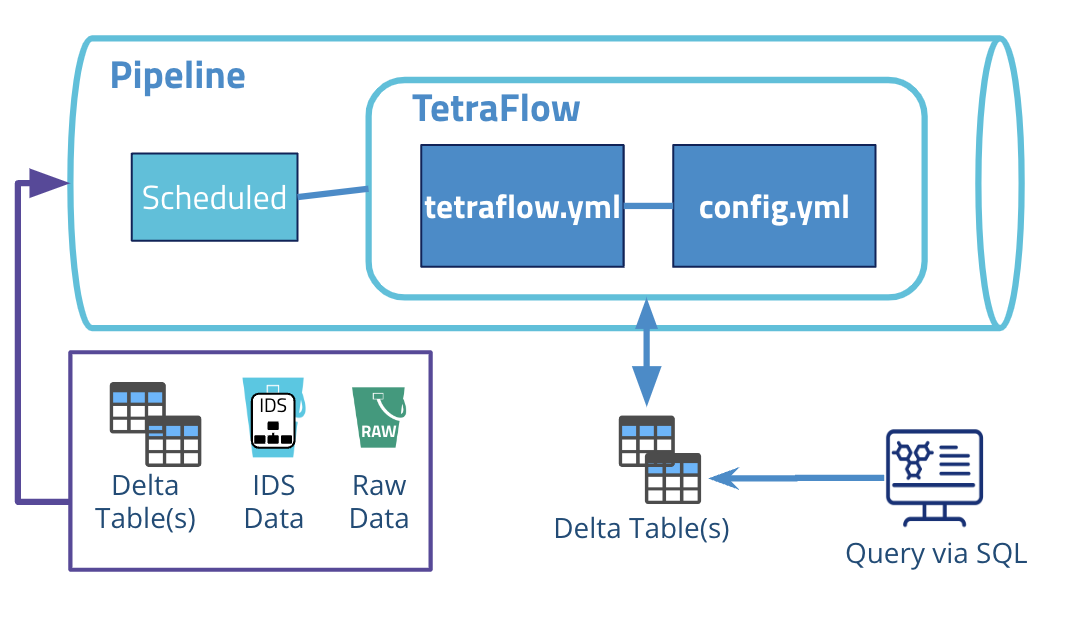
The diagram shows the following workflow:
-
The Tetraflow pipeline is configured with a Scheduled Trigger and is set to run at a specific time.
-
The Tetraflow pipeline runs a predefined SQL workflow that defines the path to the data source (
source), transformation logic (processor), and the target Lakehouse table(s) (sink). -
When processing is finished, output files are then indexed according to the predefined Lakehouse tables and stored in the Data Lakehouse. Through this process, the data becomes easily accessible through an AI/ML-ready data storage format that operates seamlessly across all major data and cloud platform vendors. The data also remains available through search in the TDP user interface, TetraScience API, and SQL queries.
Working with Schemas
Tetraflow pipelines interact with three types of schemas in the Data Lakehouse, each with specific read and write permissions:
- Internal (IDS) schemas: read-only IDS Lakehouse tables that are automatically generated by the TDP when you convert data to Lakehouse tables.
- External schemas: custom schemas that your Tetraflow pipeline creates and that are specific to your organization
- Default schemas: schemas generated using the TDP v4.2.x limited availability release Data Lakehouse Architecture and Normalized IDS Lakehouse tables, which include the
file_infoandfile_attributestables
Tetraflow Schema Permissions
| Schema Type | Read access | Write access |
|---|---|---|
| Internal (IDS) Schemas | Yes | No |
| External Schemas | Yes | Yes |
| Default Schemas | Yes | Yes |
Create a Tetraflow Pipeline
To create a Tetraflow Pipeline, first create a Tetraflow that defines your transformation logic in SQL. Then, create a new Pipeline that uses the deployed Tetraflow.
Prerequisites
Before you can complete the following procedure, you must complete the Self-Service Pipeline (SSP) Setup and Prerequisites. The prerequisites for creating Tetraflows are the same as Self-Service Pipelines.
Make sure that you also have the following:
- Python version 3.7 or later
pipPython package manager- The TetraScience Command Line Interface (ts-cli). To install the ts-cli, run the following command in your local terminal:
pip3 install tetrascience-cli - Knowledge of Spark Structured Query Language (SQL) Syntax
- Appropriate permissions to create and deploy artifacts to the TDP
Step 1: Create a Tetraflow Artifact
Create a Tetraflow artifact by doing the following:
-
In your local terminal, create a directory for your Tetraflow.
-
Navigate to the directory and run the following command:
ts-cli init tetraflowThe command creates a
tetraflow.ymlandmanifest.jsonfile in the directory. You will define your Tetraflow logic in thetetraflow.ymlfile. Themanifest.jsonfile contains metadata, configuration, and specifications for the Tetraflow. Themanifest.jsonfile serves as the source of truth for each artifact's metadata and tells the Tetra Data Platform (TDP) how to discover, deploy, and display each artifact in the user interface. -
Configure the
manifest.jsonfile with at least the following minimum required fields:
typenamespaceslugversion
For an example manirest.json file and more information about configuring optional fields, see SSP Artifact manifest.json Files.
- Edit the
tetraflow.ymlfile based on your use case. Make sure that you define the following properties:name: Defines the name of the Tetraflow that appears in the Tetra Data Platform (TDP)config: Defines the Tetraflow Pipeline's runtime settingsNOTEThe
configparameter sets configurable parameters that are passed to subsequent steps in your Tetraflow. These steps appear in the pipeline configuration UI for users to provide their input.input: (category: source): Defines the path to your data source (you must replaceinputwith the name of the data source)transform: (category: processor): Defines your transformation logic in SQL (you must replacetransformwith a short name for the SQL statement)output: (category: sink): Defines the target Delta Table(s) (you must replaceoutputwith a short name for the output action)library: Defines a Tetraflow library (latest version:0.1.37)
NOTETo enhance Tetraflow functionality and prevent incorrect dependency resolution, defining an explicit
libraryversion is now required. Defining a library version overrides the default artifact builder behavior of automatically selecting the highest version configuration file.
tetraflow.yml File Example
tetraflow.yml File ExampletetraflowSchema: v1
library: 0.1.37
name: My Tetraflow
options:
batchMode: true
framework: spark
config:
<input>:
label: "Input Table Name"
description: "Name of the table to read from"
type: string
required: true
output:
label: "Output Table Name"
description: "Name of the table to write to"
type: string
required: true
workflow:
input:
type: Delta
category: source
description: Read the input dataset
properties:
table_name: $( full_table_name('table_name_v') )
<transform>:
type: Sql
category: processor
description: Transform the dataset
needs: input
properties:
sql: |
SELECT field_1, field_2 as config_input
FROM input
<output>:
type: Delta
category: sink
description: Write the transformed data out
needs: transform
properties:
table_name: $( full_table_name('table_name_v') )
mode: overwrite
constraints:
trigger:
type: file <can also be `scheduled` or `[file, scheduled]`, based on the trigger type>config Parameters
config ParametersIn the config property, enter the following information:
- In the
input:section, forlabel:Enter the source Intermediate Data Schema (IDS) table's name. - In the
output:section, forlabel:Enter a name for the target Lakehouse table (Delta table) that you want to create.
config Property Example
config Property Exampleconfig:
input:
label: "Input Table Name"
description: "Name of the table to read from"
type: string
required: true
output:
label: "Output Table Name"
description: "Name of the table to write to"
type: string
required: trueSource (input) Parameters
input) ParametersIn the Workflow section, for the input (category: source) property, enter the following information:
- Replace
inputwith the name of the data source (for example,empowerorchromeleon. - For
table_name:, enter the source IDS table name in the following format:$( full_table_name('table_name_v') )(For example,table_name: $( full_table_name('lcuv_empower.lcuv_empower_v18') ))
NOTEYou can source data from multiple tables in the scope of a single workflow by adding more
inputcode blocks.
Source (input) Property Examples
input) Property ExamplesInternal (IDS) Schema Source Example
Internal (IDS) schemas are read-only IDS Lakehouse tables that are automatically generated by the TDP when you convert data to Lakehouse tables. To access IDS Schemas, you must explicitly specify the schema name.
<input>:
    type: Delta
    category: source
    description: Read the input dataset
    properties:
      table_name: $( full_table_name('akta.table_name_v') )
External Schema Source Example
External schemas are custom schemas that your Tetraflow pipeline creates and that are specific to your organization. By default, if you use the full_table_name expression without specifying a schema, the tables are saved in the external schema.
<input>:
    type: Delta
    category: source
    description: Read the input dataset
    properties:
      table_name: $( full_table_name('table_name_v') )
Default Schema Source Example
Default schemas are tables generated using the TDP v4.2.x limited availability release Data Lakehouse Architecture and Normalized IDS Lakehouse tables, which include the file_info and file_attributes tables. To access Default Schemas, you must explicitly specify the schema name.
<input>:
    type: Delta
    category: source
    description: Read the input dataset
    properties:
      table_name: $( full_table_name('default.table_name_v') )
Processor (transform) Properties
transform) PropertiesIn the Workflow section, for the transform (category: processor) property, enter the following information:
- Replace
transformwith a short name of the SQL statement. - For
description, enter a short description of the SQL statement. - For
needs, enterinput. - For
sql, enter transformation logic for your pipeline by creating one or more SQL statements in Spark SQL syntax. Make sure that the statements can operate on any of the tables that you defined in theinputproperty.
NOTEYou can process data with multiple SQL statements in the scope of a single workflow by adding more
processorcode blocks.
Processor (transform) Property Example
transform) Property ExampleThe following transform property example defines a processor that will extract the peaks data from Empower, Chromeleon, and Unicorn IDS tables:
peaks:
    type: Sql
    category: processor
    description: Harmonization peaks tables (silver)
    needs: input
    properties:
      sql: |
        WITH empower_peaks AS (
        SELECT
            file_id AS injection_uuid,
            file_id AS result_uuid,
            file_id AS peak_uuid,
            file_id AS peak_id,
            rp2.amount.value AS amount_value,
            rp2.analyte AS analyte,
            rp2.area.value AS area_value,
            rp2.area.percent.value AS area_percent,
            rpw2.value AS peak_width,
            rp2.resolution.value AS resolution,
            rp2.retention.time.value AS retention_time,
            rp2.signal_to_noise.value AS signal_to_noise_ratio,
            rp2.symmetry_factor.value AS symmetry_factor,
            rp2.usp_tailing_factor.value AS usp_tailing
        FROM (
            SELECT file_id, rp , rpw
            FROM empower
            LATERAL VIEW EXPLODE(results.peaks) AS rp
            LATERAL VIEW EXPLODE(rp.widths) AS rpw
        )
        LATERAL VIEW EXPLODE(rp) AS rp2
        LATERAL VIEW EXPLODE(rpw) AS rpw2

        ),
        chromeleon_peaks AS (
        SELECT
        file_id AS injection_uuid,
        file_id AS result_uuid,
        file_id AS peak_uuid,
        file_id AS peak_id,
        rp.quantification.amount.value AS amount_value,
        rp.identification.name AS analyte,
        rp.quantification.area.value AS area_value,
        rp.quantification.area_percent.value AS area_percent,
        rp.resolution.peak_width.base.value AS peak_width,
        rp.resolution.calculated.value AS resolution,
        rp.retention.time.value AS retention_time,
        rp.statistics.signal_to_noise.value AS signal_to_noise_ratio,
        rp.statistics.symmetry.value AS symmetry_factor,
        rp.baseline.capacity_factor.value AS usp_tailing
        FROM chromeleon
        LATERAL VIEW EXPLODE(results) AS r
        LATERAL VIEW EXPLODE(r.peaks) AS rp
        ),
        unicorn_peaks AS (
        SELECT
        file_id AS injection_uuid,
        file_id AS result_uuid,
        file_id AS peak_uuid,
        file_id AS peak_id,
        '' AS amount_value,
        rp.name AS analyte,
        rp.area.value AS area_value,
        rp.area_percent.value AS area_percent,
        rp.width.value AS peak_width,
        rp.resolution.value AS resolution,
        '' AS retention_time,
        '' AS signal_to_noise_ratio,
        '' AS symmetry_factor,
        '' AS usp_tailing
        FROM akta
        LATERAL VIEW EXPLODE(result.peaks) AS rp
        )
        SELECT * FROM empower_peaks
        UNION ALL
        SELECT * FROM chromeleon_peaks
        UNION ALL
        SELECT * FROM unicorn_peaks
Sink (output) Property
output) PropertyIn the Workflow section, for the output (category: sink) property, enter the following information:
- Replace
outputwith a short name for the output action. - For
needs, enter the name of the required SQL statement input that you created in theprocessorproperty. - For
table_name, enter the target Lakehouse table name that you want to create in the following format:$( full_table_name('table_name_v') ). You can write to either External or Default schemas:- For External schemas, enter the following:
table_name: $( full_table_name('peaks') )(recommended) - For Default schemas, enter the following:
table_name: $( full_table_name('default.peaks') )
- For External schemas, enter the following:
NOTEKeep in mind the following when configuring your sinks:
- You can transform source data into multiple Lakehouse tables in the scope of a single workflow by adding more
sinkcode blocks.- Always write to a new schema table. Writing to the default schema table is not recommended. IDS schemas are read only.
Sink (output) Property Example
output) Property ExampleThe output property example writes the peaks processor data extracted in the the previous transform property example toa peaks Lakehouse table.
write_peaks:
    description: Write the peaks table
    type: Delta
    category: sink
    needs: peaks
    properties:
      table_name: $( full_table_name('peaks') )
      mode: overwrite
      options:
        delta.minWriterVersion: 2
        delta.minReaderVersion: 1
        delta.enableDeletionVectors: false
Constraints (constraints) Property (Optional)
constraints) Property (Optional)
NOTE
privatenamespace Tetraflows that don't contain aconstraintsparameter that defines them as having a scheduled trigger won't appear in the Select Protocol tab when the SCHEDULED trigger check box is selected on the Pipeline Edit page.
Type: Object
The optional constraints property defines the Tetraflow's trigger type (file based or scheduled).
constraints Property Example
constraints Property Exampleconstraints:
trigger:
type: file <can also be `scheduled` or `file, scheduled`, based on the trigger type>Step 2: Deploy the Tetraflow Artifact
To deploy the Tetraflow artifact to to your TDP environment, do the following:
- Make sure that the local
auth.jsonfile you created while completing the setup and prerequisites is formatted correctly.
Example auth.json file
{
    "api_url":"<TDP API endpoint base URL>",
    "auth_token":"<service token you generated>",
    "org":"<your organization slug name>",
    "ignore_ssl": <true to allow invalid SSL certificates>
}- In your local terminal, navigate to the directory that contains the Tetraflow by running the following command:
cd <directory-name>
- Deploy the Tetraflow artifact by running the following command:
ts-cli publish --config ./path_to_config
Step 3: Create a Pipeline by Using the Deployed Tetraflow Artifact
To use your new Tetraflow in the TDP, create a new pipeline that uses the Tetraflow that you deployed.
When creating the pipeline, make sure that you do the following:
- When you select a trigger, select the SCHEDULED TRIGGER check box.
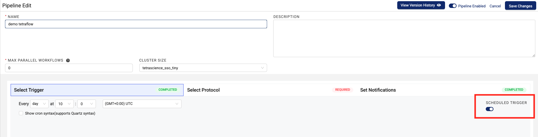
- Enter a specific, recurring time for the Tetraflow Pipeline to run on. The minimum time interval is a
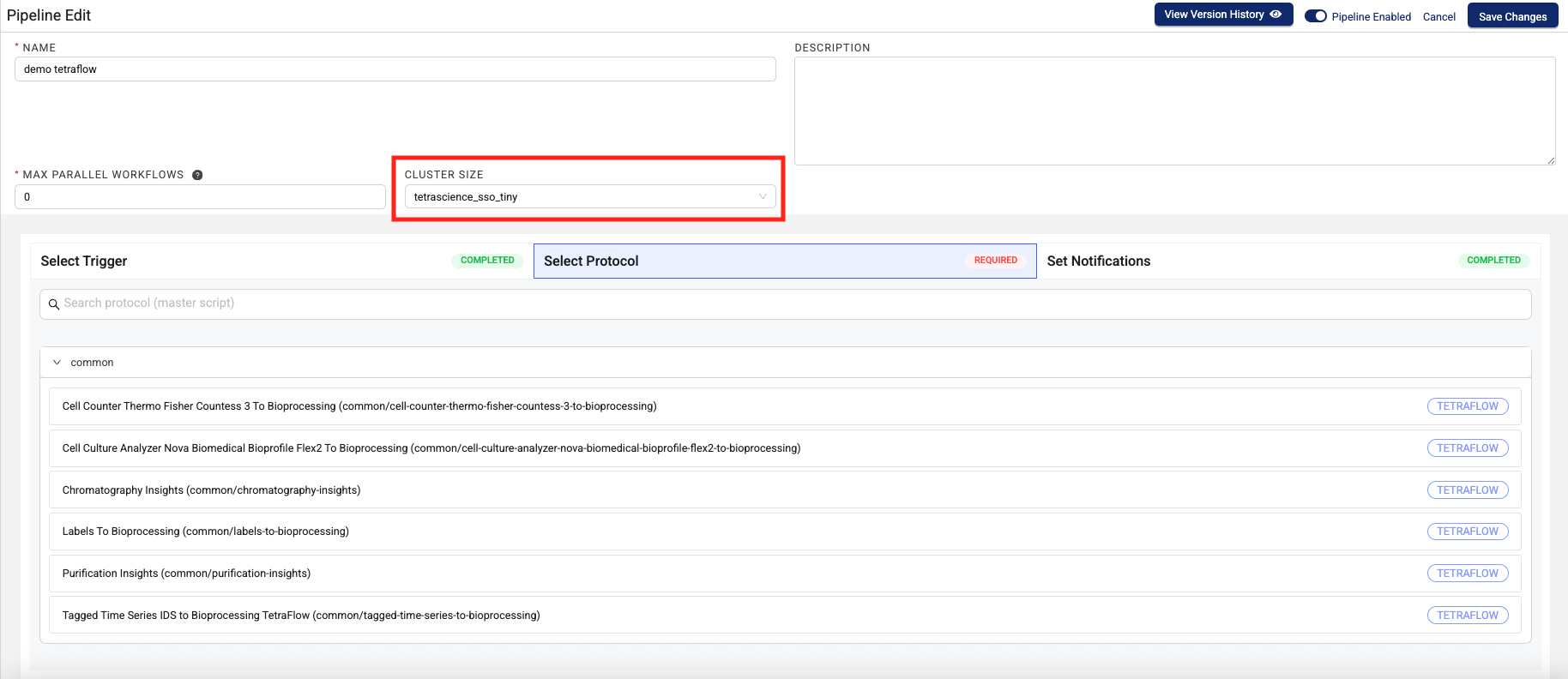
minute. The maximum time interval is ayear. - When you select a protocol, choose the Tetraflow that you created from the list.
- Configure the CLUSTER SIZE setting to define the size of the cluster that you want the TDP to spin up to run your Tetraflow Pipeline. For most use cases, the default Tiny cluster size is most appropriate.
 IMPORTANT
Always start testing your Tetraflow use case on the Tiny cluster size. If your workflow runs out of memory or takes much longer than you’re expecting, then try a size up and repeat. Doing this will help you manage the associated infrastructure costs for running Tetraflows more efficiently.
For more information, see Set Up and Edit Pipelines.
Monitor Tetraflow Pipeline Processing
To monitor Tetraflow Pipeline Processing, files, workflows, and logs, do the following:
-
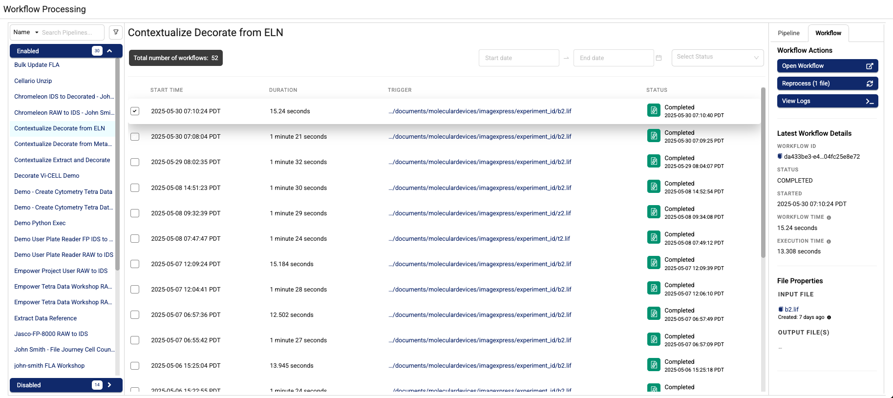
In the left navigation menu, choose Pipelines. Then, choose Workflow Processing. The Workflow Processing page appears.
-
To find a specific Tetraflow Pipeline, type the pipeline's name in the upper left search box. To filter your search by workflow date, enter a date range in the Start Date - End Date field. To filter by workflow status, select a status from the Select Status drop-down menu.
NOTEThe number of active workflows and historical workflows display near the top of the page. The active workflows count shows all workflows that are pending or currently being processed. The historical workflows count represents workflows that have been completed or have failed. If workflows are active, you can select the refresh button next to it to view the latest status.
-
Select a workflow. Two tabs appear in the right panel:
- The Pipeline tab provides a link that will take you to a page where you can edit your pipeline, scan for unprocessed files, create a bulk pipeline process job, cancel pending workflows, and view high-level triggers, and Tetraflow details.
- The Workflow tab provides links to open workflows and view workflow logs.
Run a Tetraflow Pipeline Manually
To run a Tetraflow Pipeline manually, do the following:
- Open the Workflow Processing page.
- Select the Tetraflow Pipeline that you want to run.
- Select the right Pipeline tab.
- Choose Run Now. The Tetraflow Pipeline that you selected runs.
Edit a Tetraflow Pipeline
To edit a Tetraflow Pipeline, do the following:
- Open the Workflow Processing page.
- Select the Tetraflow Pipeline that you want to edit.
- Select the right Pipeline tab.
- Choose Edit Pipeline. The Pipeline Manager page appears.
For more information about how to edit pipelines, see Set Up and Edit Pipelines.
Unpublish Tetraflows
To unpublish a Tetraflow artifact in the private namespace, run one of the following commands:
For artifacts that have a manifest.json file
ts-cli unpublish {artifact-folder} -c {auth-folder}/auth.jsonFor artifacts without a manifest.json file
ts-cli unpublish --type {artifact-type} --namespace private-{TDP ORG} --slug {artifact-slug} --version {vx.x.x} {artifact-folder} -c {auth-folder}/auth.jsonUnpublished artifacts will no longer appear in the Artifacts menu options in the TDP user interface.
Documentation Feedback
Do you have questions about our documentation or suggestions for how we can improve it? Start a discussion in TetraConnect Hub. For access, see Access the TetraConnect Hub.
NOTEFeedback isn't part of the official TetraScience product documentation. TetraScience doesn't warrant or make any guarantees about the feedback provided, including its accuracy, relevance, or reliability. All feedback is subject to the terms set forth in the TetraConnect Hub Community Guidelines.
Updated 3 months ago